
Wireless E.V. Charging Roadway
Progress Log (Group)
(Click below to Expand or Collapse)
Nov 26th-Dec 2nd
Website completion, report completion, design testing completion was done. Only task left is Powerpoint presentation and practicing the presentation.
Nov 19th-Nov 25th
Both Norman and Patrick worked extensively to update and complete the report, taking pictures and videos, and organizing data. Norman worked on power point for presentation purposes.
Norman organized and cleaned the routing of wires on both the roadway system and the vehicle system to better display the prototype in images and demonstration purposes.
Norman designed, re-worked, clarified, and updated the senior design webpage to show current senior design proposal and senior design project information.
Nov 12th-Nov 18th
Vehicle and Roadway Updates:
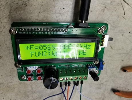
Both Norman and Patrick worked extensively on both improving the roadway and vehicle systems, each sharing and undertaking many tasks. Both Norman and Patrick conducted tests and verifications. All data has been recorded. The PWM and DC to AC conversion has been simplified by utilizing high frequency function generator. This allows us to adjust to proper resonance frequency, easily modify input power, and generate better waveforms. The output current of this function generator is lower than required, therefore we remedied this with an AC amplification circuit. Attempts to increase output power were made by utilizing an amplification circuit or MOSFET driver/buffer to increase the input power prior to transfer across the roadway to the vehicle. Tests utilizing this will be conducted.
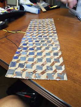
Norman completed design of the window array capacitor for the vehicle. The capacitance was measured and recorded. The capacitor was tested under misalignment and incorporated into the vehicle design to test roadway to vehicle charge.
Both Norman and Patrick worked on updating and writing on the report, figures, videos, and images. Data needs to be continually and properly organized and updated accordingly, with proper figures and tables matching. Circuitry design for each variance in the impedance network improvement and modification needs to be organized and updated accordingly with proper figures and tables matching. Much data organization to be done!
Report and Findings Updates:
Results were recorded, videos of testing coming shortly. Patrick improved upon the capacitor design. Norman improved upon roadway design and mobility. Both Norman and Patrick conducted non-conductive roadway tests and began recording data and conducting conductive roadway tests. Norman designed, re-worked, clarified, and updated the senior design webpage to show current senior design proposal and senior design project information.
Image 1: Window Array Capacitor Image 2: MOSFET Amplification
Circuit (Testing)
Image 3: High Frequency Function Generator

Nov 5th-Nov 11th
Vehicle and Roadway Updates:
Both Norman and Patrick worked extensively on both improving the roadway and vehicle
systems, each sharing and undertaking many tasks. Efforts to reduce vehicle slippages were undertaken as well as modifications to barriers and edges along the roadway to improve vehicle mobility utilizing parchment paper and staples. Both Norman and Patrick conducted tests and verifications. All data has been recorded.
Patrick also focused on the potential methods to reduce capacitor size on the vehicle while
increasing capacitance. A window-row array capacitor was found, and had very good results under
misalignment. Data needs to be properly organized and updated accordingly, with proper figures and tables matching.
Circuitry design for each variance in the impedance network improvement and modification
needs to be organized and updated accordingly with proper figures and tables matching. Much data
organization to be done!
Report and Findings Updates:
Results were recorded, videos of testing coming shortly. Patrick improved upon the capacitor design. Norman improved upon roadway design and mobility. Both Norman and Patrick conducted non- conductive roadway tests and began recording data and conducting conductive roadway tests. Norman designed, re-worked, clarified, and updated the senior design webpage to show current senior design proposal and senior design project information.
Video 1: Non-Charging Roadway Test
Oct 29th-Nov 4th
Vehicle and Roadway Updates:
Both Norman and Patrick worked extensively on both improving the roadway and vehicle systems, each sharing and undertaking many tasks. Efforts to reduce vehicle slippages were undertaken as well as modifications to barriers and edges along the roadway to improve vehicle mobility. Both Norman and Patrick conducted tests and verifications. Tests for the vehicle with a non-conductive roadway were taken, utilizing a stopwatch and approximating the time until the battery life of the vehicle was too low to base upon vehicle load requirements. It was noted that approximately 40% to 50% of all non-conductive roadway tests fell between 1hr 59min 33secs to about 2hrs 5min 15secs. This value raised to 70% of all non-conductive roadway tests when in the range of 1hr 59min 33secs to about 2hrs 12min 3secs, with the remaining 30% of tests exceeding this range. All of this data has been recorded.
Patrick also focused on the impedance matching network and starting conductive roadway tests. Tests between the H-bridge series L resonant circuit and Class E power amplification circuit were made based upon the simplicity and difficulty in reaching impedance matching in order to improve upon power tests. Utilizing the Class E power amplification circuit, the frequency range could increase from 500k Hz to 5MHz, depending on the resonant frequency of the impedance matching network and coupling capacitors, therefore a function generator circuit instead of an Arduino is being utilized to change the frequency beyond the limitations of the 1MHz defined by the Arduino specifications. The circuit still operates the in the same role as a pulse width modulation but allows for a broad spectrum with easier accessibility in changing the frequency to match the required resonant frequency.
Data needs to be properly organized and updated accordingly, with proper figures and tables matching. Circuitry design for each variance in the impedance network improvement and modification needs to be organized and updated accordingly with proper figures and tables matching. Much data organization to be done!
Report and Findings Updates:
Results were recorded, videos of testing coming shortly. Patrick improved upon impedance matching circuit and updated the circuit in Proteus for ease in adjustments during the troubleshooting procedure while recording tests and data. Both Norman and Patrick conducted non-conductive roadway tests and began recording data and conducting conductive roadway tests. Norman designed, re-worked, clarified, and updated the senior design webpage to show current senior design proposal and senior design project information.

Oct 22nd-Oct 28th
Norman continued to secure the body with more bracing to the chassis, utilizing more points for the nuts to bolt onto the chassis. The roadway circuit was organized, while Patrick worked extensively, tweaking the roadway system. The bolts were trimmed and shaved according to the maximum height the body needed to be on the chassis. The circuit was redesigned once more, adjusting capacitors and inductors for L-Compensation circuit. With a slightly better efficiency on the circuit.
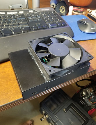
The roadway circuit also required a much better cooling system, so a 120mm fan was installed, with a spare HDD case being used as a mount for the fan.
Image 1: Roadway System Exterior Image 1: Roadway System Exterior

Oct 15th-Oct 21st
Norman painted and secured the body of the vehicle to the chassis utilizing nuts, large screws, high temperature adhesive, and L-bars. Both Norman and Patrick worked extensively on both the roadway and vehicle systems, each sharing and undertaking many tasks. It was noted that for aesthetics that the screws will need to be trimmed after testing and troubleshooting. The rectifier circuit was re-created utilizing individual Schottky diodes instead of Schottky MOSFETS. The vehicle has begun testing, troubleshooting, and measurements procedure. The current output power is lower than expected, but was able to charge from the roadway system to the vehicle while under operation, though when the vehicle was under operation, the transferred power was able to supplement the system, but not able to completely operate the system and charge the battery. Our AC transferred power pre-rectification is well within 70% to 80 % efficiency, but after rectification, this is around 55% to 60% efficient. The efficiency was hard to determine under operation and load without a new installed voltmeter after rectification. Under perfect ideal conditions, the simulated efficiency is 96% efficient. When the vehicle was not in motion, the battery was able to get a charge, though this value was still low. This, after troubleshooting, has been narrowed down to four possibilities: Insufficient input voltage, errors with gate voltage routing, variance in impedance matching network, lack of voltage regulator or buck-boost. Rerouting and re-organizing the vehicle system will be accomplished this week in further troubleshooting and efficiency measurements.
Vehicle guidance system was design and proposed utilizing digital logic and sensory instead of a microprocessor for guidance. This will be tested this week. Our last voltmeter and ammeter sensor pinout could not work in measuring voltage from the rectifier, so ordering of that part was made and to be delivered this week. A buck-boost circuitry was ordered for voltage regulation for after.
Both Norman and Patrick continued troubleshooting and refining the roadway system. A fan was necessary to add to our full bridge switching circuitry and gate drivers to maintain proper temperature levels. A higher input voltage system is currently being designed and evaluated. Routing and organizing the roadway circuitry into a single ESD safe container. Additionally, the gate voltage is undertaking testing and troubleshooting.
Results were recorded, videos of testing coming shortly. Patrick re-designed and updated the circuit in Proteus for ease in adjustments during the troubleshooting procedure. Both Norman and Patrick updated the Parts and Materials Cost as necessary. Updates displaying results, showing verifications, and updating block diagram is necessary. Norman designed, re-worked, clarified, and updated the senior design webpage to show current senior design proposal and senior design project information.
Oct 8th-Oct 14th
Both Patrick and Norman began testing and troubleshooting vehicle build. It was found that the voltage regulation and current regulation from the rectified power transferred signal to the battery system was unnecessary as the voltage and current parameters were well within design parameters. Additionally, it was found that more issues in regards to passing the rectified power transferred signal would only pass through the voltage and current regulator at certain values, which proved unnecessary in our build design. Patrick adjusted the rectifier to increase transfer efficiency into a full-wave rectifier consisting of Shottky diodes, as these diodes were best for high frequency signals. Patrick also found that to simplify the impedance matching network, the circuit design of a LC compensating network could be developed into a series L compensating network instead. Both Patrick and Norman soldered, tested, and adjusted the vehicle and roadway systems based on these findings.
Norman began painting and cutting the body for the vehicle. It was discussed whether to implement a guidance assistant system on the vehicle for better roadway alignment by utilizing either attached wheels on the body of the vehicle, or by utilizing digital logic to control current flow to the motors based upon a red LED and photodiode, which could potentially detect the sides of the roadway guidance track and allow the vehicle to realign.
Both Norman and Patrick continued testing and making adjustments to the roadway system. Both Norman and Patrick continued verification process for each block component as specified in the Engineering Requirements and the Task Decomposition, Roles, and Responsibilities . Patrick updated the Engineering Requirements table to dis-include the voltage and current.
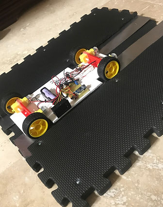
With the implementation of the series L compensating network circuit and the full-wave rectifier, the system successfully transferred power from the roadway system to the vehicle system at about a 70% efficiency. To better analyze and visual the power transfer, it was discussed to potentially implement additional voltage and ammeters at post-rectification as well as across just the battery supply. Currently, the voltage and ammeter is positioned across the entire vehicle load.
Norman designed, re-worked, clarified, and updated the senior design webpage to show current senior design proposal and senior design project information.
Image 1: Testing of "Roadway to Vehicle" Power Transfer

Oct 1st-Oct 7th
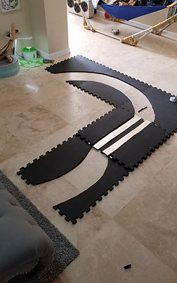
Norman continued work on the roadway system pathing, implementing curves and the circular design for better testing and analysis of the system. Patrick completed the soldering and design for the roadway system circuitry, as well as the impedance matching network on the vehicle system. Both Norman and Patrick began documenting and performing the validation of components as per the Engineering Requirements, as well as the evaluation for the components. Patrick further updated the parts and cost list, which included the vehicle parts total cost, roadway parts total cost, tools total cost, feasibility testing parts total cost, and an overall total cost. This will be compared to our estimated cost from Senior Design Proposal.
Additionally, final further adjustments in vehicle design were discussed, which included a turning axle for the front wheels, to allow for better alignment on the roadway.
Norman designed, re-worked, clarified, and updated the senior design webpage to show current senior design proposal and senior design project information.
Image 2: Construction of Roadway
Image 1: Measurement of dimensions of Vehicle
for the design of Roadway
Sept 24th-Sept 30th
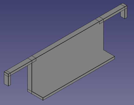
Patrick completed designing vehicle build. Both Norman and Patrick began and completed the building of roadway build. Patrick created the 3D design for the axle and made necessary adjustments.
Both Norman and Patrick begin verification process for each block component as specified in the Engineering Requirements and the Task Decomposition, Roles, and Responsibilities . Patrick updated the Engineering Requirements table to include the voltage and current regulator for the battery supply, Being more specific on the coupling capacitive plate portion, and adding the switch.
Norman updated our timeline for better comparison and observation between proposed timeline and actual timeline. Norman added a tools list table with both a purpose and cost section to show what specific tools were necessary for implementation.
Patrick updated both the vehicle parts and cost list as well as the roadway parts and cost list. Additionally, final necessary adjustments in design, measurements, and parts for the vehicle system where made in order to complete and test the entire system for the following week.
Norman designed, re-worked, clarified, and updated the senior design webpage to show current senior design proposal and senior design project information.

Sept 16th-Sept 23rd
Utilizing our order parts and vehicle build blueprint, both Norman and Patrick began building vehicle build. Testing and verification the operation of each component that was added to the vehicle, and multiple speeds were calculated. Adjustments were made on attaching certain components by utilizing Velcro instead, in order to adjust the position of key components on the vehicle such as the motor, battery, and breadboard containing the potentiometer, switch, and rectifier. It was observed that we should add a sort of axle bar between each of the pairs of motors because when utilizing Velcro to attach the motors, the motor and wheel tilted slightly inward, which with a bar would allow for both better alignment and position for the motor and wheels. This will also raise the chassis of the vehicle slightly and improve performance for the vehicle. It was observed prior to the addition of the impedance matching network and the coupling capacitive aluminum plates, that the voltage output of the battery was “4.1v”, the current output of the battery was “150mA”, and the power of the battery “0.615W”. We tested to verify that charging of the battery could be observed by supplementing the system with external charging, and the current decreased, showing that less output power was necessary by the battery. It was also observed that to attach and solder wires to aluminum plates while maintaining as flat as a surface as possible to maintain coupling capacitance that solder with a higher quantity of flux was necessary.
Both Norman and Patrick began the organizing of ordered parts, measurements, and design of the roadway system necessary to build the roadway system for the following week. Additionally, final necessary adjustments in design, measurements, and parts for the vehicle system where made in order to complete and test the entire system for the following week.
Patrick began the re-work, simplification, and clarification of the materials (Vehicle and Roadway) and tools list, updating and noting necessary additions observed when building key components.
Norman designed, re-worked, clarified, and updated the senior design webpage to show current senior design proposal and senior design project information.
Sept 3rd - Sept 9th
This entire week, nothing could be accomplished, because parts were delayed due to weather conditions (hurricane Dorian). School was also off, so no on-campus activities or meetings could be done with Professor Ejaz.
Aug 29th - Sept 2nd
This week, discussion of what parts needed to be ordered, alongside with what problems needed to be clarified with the professor was done. It was also the first week of the first meeting, therefore not much was accomplished beforehand. This week, things were cut short in order to prepare for the upcoming hurricane that was to occur.
Sept 10th - Sept 16th
Re-designed and Simplified Engineering Specifications. Discussed necessity to outline blueprints in software. Patrick tested potential quality improvements on power transfer system and methodology implementation with our current design components. Patrick determined that the system should work based on theoretical, simulated, and experimental results but the necessity to focus on minimizing technical issues and instead focusing on quality improvements was important for success.
Norman tested and measured our vehicle system current, voltage, and power requirements with respect to vehicle forward and turning motions as well as the vehicle system battery. Norman also tested and measured potential substitute system’s current, voltage, and power requirements with respect to basic motor propulsion as well as potential substitute vehicle system batteries. Norman compared, analyzed, and communicated extensively the results while ensuring that the components would still meet project parameters and the required tests. Norman determined that our current desired vehicle and roadway system implementation needed vast quality improvements and a re-focus from technicality issues to dynamic wireless power transfer.
We both discussed with respect to roadway design a need to cut vehicle pathing for improved measurements on the roadway system as well as maintaining vehicle control. We both discussed with respect to design implementation the need to have plating as close to vehicle without
dielectric material in-between plates or any other potential interference in the wireless power transfer procedure. We both discussed potential implementation of FPGA utilizing VHDL for PWM, will be explored further. We concluded that it was important to have an overall design system emphasis on dynamic power transfer capabilities, not technicalities of environmental or vehicle design improvements and instead leaving those technicalities for the discussion on future work. We both discussed the need to re-work, simplify, and clarify project final report, block diagrams, timelines, materials lists, tools list, and software list.
Norman designed, re-worked, clarified, and updated the senior design webpage to show current senior design proposal and senior design project information.
The following list was conjured up for the vehicle:
Current Vehicle Part List:
- 1x Pushbutton Switch
- 4x DC Motors (Adafruit)
- 4x 40mm Tires
- 4x 40mm wheels
- 1x Potentiometer
- 1x Non-conductive chassis
- 1x AC to DC High Frequency Rectifier
- 1x 18650 Lithium Battery
- 1x 18650 Lithium Battery Holder/Case
- Plastic Screws, bolts, nuts for component attachment (Non-conductive)
- 1x Voltmeter and Ammeter Measurement Component
- 1x USB External Power Bank (Simplification for proper vehicle charging for Lithium Ion
Battery)
- 2x Aluminum Plates
- 1x Impedance Matching Network Components
- Breadboard
- Wires
- Solder
- Hot glue
The following list was conjured up to complete the roadway:
Current Roadway Part List:
- 1x Yoga Puzzle Matt Block (Black)
- 2x Aluminum Plate
- 1x Arduino Uno (PWM)
- 1x IRF 510 MOSFET
- 3x 12v DC Power Supply (1 For system Power supply, 1 for Driver Power Supply, 1 for
Arduino Uno PWM Power Supply… The Driver and Arduino Uno can be utilized for multiple
circuits.
- 1x TC4422 MOSFET Driver
- 1x Impedance Matching Network Components
- Breadboard
- Wires
- Solder
- Hot Glue

